Work Injury Detection with FeetMe
Introduction
Under the National Overseas Program (NOC) with NUS, I had the opportunity to intern at FeetMe, a French MedTech startup. The company's main product are their high-tech insoles. The insoles are used to perform gait assessment and help with rehabilitation with real-time biofeedback.
At FeetMe, I was under the research team and focused on developing the hardware behind a body motion tracking electronics wearable. The goal was to create a wearable that could collect data on a user's motion which could be used to alert the user if he had bad posture - i.e in positions that had a high chance of developing work-related musculoskeletal injuries.
My work was split into 2 parts
- Initial prototype by using Opensim and an open-source research paper
- Full-stack hardware development of a second prototype prioritizing comfort
Main Topics from creating a Real-Time Motion Tracking Wearable
-
Embedded Systems: Architected a Zephyr RTOS firmware stack on the nRF5340. Bypassed Device Tree limitations by porting vendor C-drivers to support dynamic runtime initialization of multiplexed sensors.
-
Hardware Design: Designed and manufactured high-density PCBs using Altium Designer, optimizing for a thin and small form factor.
-
Bus Optimization: Replaced software-addressed I2C multiplexing with a GPIO-toggled analog switching architecture, reducing protocol overhead to maximize sensor polling bandwidth.
-
IoT Communications Developed a custom BLE service for real-time data streaming and a Python/PyQt dashboard for sensor visualization and data logging.
Opensim
When I first arrived, my first task was to study the research paper Wearable and Real-time Kinematics Estimates with OpenSense - OpenSim Documentation - OpenSim and replicate the results. However the RPI image did not work.
To do this, I had to build the project on a Raspberry Pi from scratch. It was quite challenging due to the lack of documentation in building Opensim on a resource-constrained system. However, I was able to do so after much trial and error, and have also helped others in the community by providing guidance to others wanting to do ths same via GitHub issues - Problems building Opensim on Ubuntu 20.04 for Raspberry Pi 4 · Issue #3405 · opensim-org/opensim-core
 |
 |
|---|---|
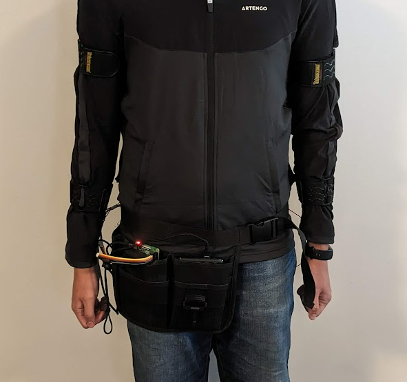
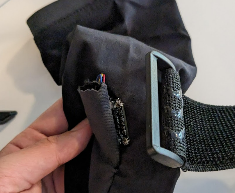
| RPI and portable charger stored at waist | IMU's secured under velcro |
Next, I was able to assemble the full system. The system consists of a Raspberry Pi, 6 IMUs and a multiplexer. I sewed them onto a jacket, and used velcro straps to tightly secure each IMU to different body parts. However, the python wrappers I needed for actual data collection did not work. Although I opened an issue, I did not get a response back in time. 'InverseKinematicsSolver' object has no attribute 'addOrientationValuesToTrack' · Issue #3415 · opensim-org/opensim-core
Full Stack Hardware Development
The next step was to create a version 2 of the prototype. The previous prototype was heavy and uncomfortable because
- The RPI and Portable charger were heavy
- The velcro straps were uncomfortable
The goal of the next prototype was to make the system more lightweight and focused. We moved away from Opensim because the software was quite black-box. The next protype simple collected IMU data and if there was time, we could study the IMU data and create algorithms to detect work injuries.
Spoiler
There wasn't time, I only finished the prototype the before I left, so I couldn't work on the algorithms. But at least i got the hardware up!
Electronics Hardware
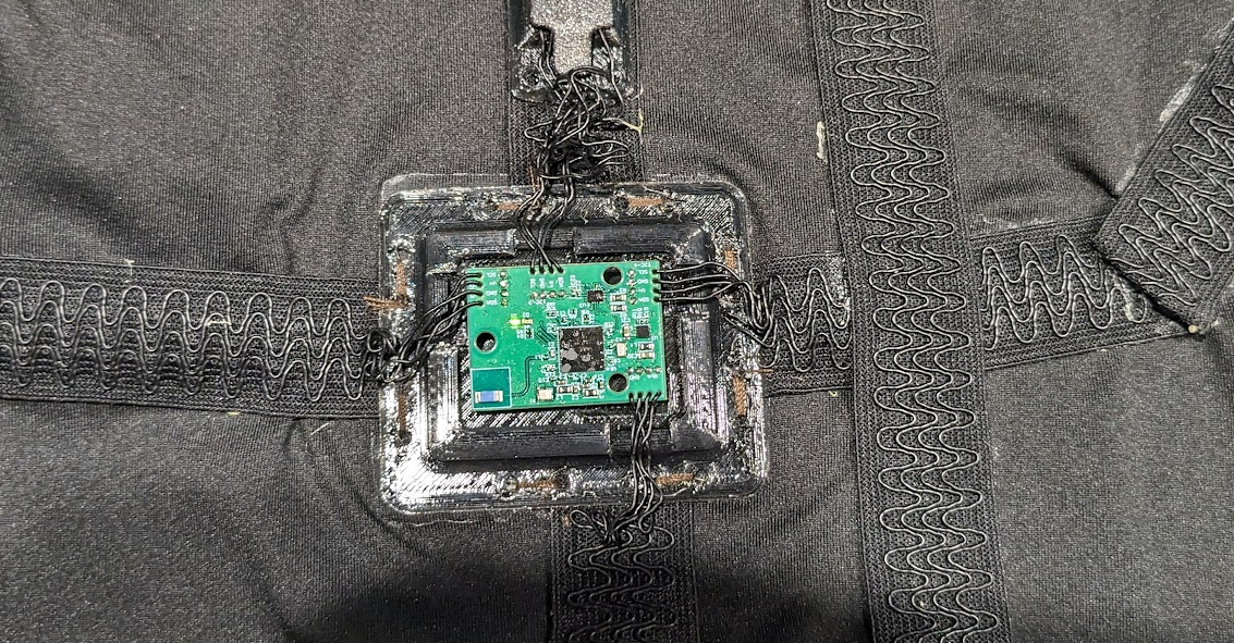
The first thing I started with was PCB Design. I used Altium designer to create and manufacture the SOC and IMU sensors. Both of them were designed to be lightweight and unobtrusive. Hence, they had tiny form factors.
Instead of using typical wires, stretchy electrical tape was also used for comfort. I can't remember how I discovered it unfortunately, but the form factor was much better than wires.
NRF5340
The Nordic 5340 was chosen as the main microcontroller because it was
- Very power efficient. Both the MCU and the sensors were powered by a coin cell which could easily last for a few hours
- Could transmit data very efficiently via Bluetooth low energy. I used a ceramic antenna for this.
The OpensenseRT design used an I2C multiplexer which could be slow due to I2C multiplexer protocol overhead. I hence migrated to an analog multiplexer mapped to separate I2C lines. This minimized switching time to a single GPIO toggle, maximizing available bandwidth for high-frequency IMU sensor polling.
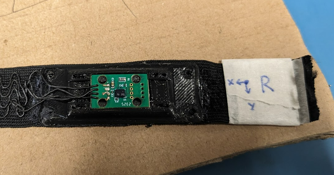
IMU
The footprint of the IMUs were heavily optimized by removing any linear regulators or pull up resistors that typical IMU breakout boards come with.
Software
I used NRF connect to program the NRF5340. There were quite a few challenges and technical hurdles namely
- Figuring out how to use BLE
- Figuring out how to use the analog multiplexer
The primary architectural challenge involved the analog-multiplexed I2C bus: because the multiplexer hides sensors at boot time, the standard Zephyr Device Tree (DT) could not initialize all six IMUs.
To bypass the DT's static initialization limitations I had to Port STMicroelectronics C drivers into the Zephyr environment, bypassing the standard driver model. This allowed for manual runtime initialization and data collection from sensors as the analog mux toggled channels, despite the non-persistent bus state.
I also had to implemented a custom BLE service for real-time streaming of 6 IMU sensors. To visualize and collect data, I wrote a Python script using PyQT and BLEAK.
Main Learning Points/Conclusion
The project was a high-intensity sprint, with final assembly and validation completed just 24 hours before the internship concluded. While the prototype was successful, the development process highlighted three critical areas for hardware iteration:
- Telemetry & Debugging: I initially relied on the JTAG interface for data logging, but I could not get it to work and relied on LEDs for debugging. I should have added a dedicated UART-to-USB bridge. Even if unused, it would have been a good backup and an additional interface
- Modularity & Serviceability: To meet the tight deadline, wires were direct-soldered to the PCB which isn't maintainable in the long run. I should have used fine-pitch connectors like JST-SH which would make the assembly more modular for serviceability (i.e easy to replace sensors if needed.)
- Power Management: The current design lacks battery fuel gauging. Integrating a simple voltage divider into an ADC channel would allow for coin-cell discharge monitoring, which would be helpful for the system.
This project was a turning point. I truely enjoyed working with custom hardware design and low-level firmware and was the main reason why I started pursuing Embedded Systems as a career. It remains the most challenging—and fulfilling—project I have worked on during my undergraduate studies.